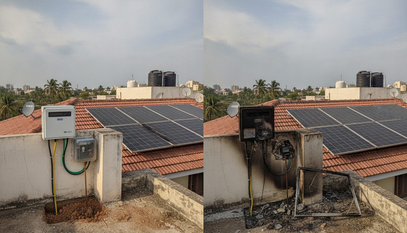
Why Solar Systems Fail During Monsoon and Grid Fluctuations
Monsoon lightning surges and grid voltage fluctuations are leading causes of residential solar inverter and PCB board failures in India. When heavy storms strike, high-voltage transients travel through overhead power lines and direct rooftop strikes. Without proper mitigation, these voltage spikes reach sensitive internal components and destroy delicate microchips within the inverter. Grid instability compounds the risk by sending unpredictable voltage surges directly into home electrical circuits.
Preventing catastrophic equipment damage requires a two-pronged defense strategy. First, an installation must isolate high-voltage surges before they enter the inverter chassis. Second, stray currents must find a safe path into the ground without passing through home appliances. Homeowners planning an installation can check space requirements using a solar roof area calculator to ensure proper equipment placement away from vulnerable roof edges.
Want to see what this means for your roof? Use our free solar calculator for India to estimate system size, cost after the ₹78,000 subsidy and payback period.
Technical Requirements for Type 2 Surge Protection Devices
A solar surge protection device earthing india configuration typically relies on Type 2 SPDs to safeguard DC and AC circuits. Type 2 SPDs act as the main defense inside the distribution box by limiting surge voltages and diverting high-energy current pulses safely away from the inverter. These devices clamp down on sudden voltage spikes originating from lightning strikes or utility switching events.
Standard safety protocols demand that SPDs are installed on both the DC side between the solar panels and the inverter, and on the AC side between the inverter and the main service panel. Using the correct ratings ensures the protection unit triggers fast enough to prevent high voltage from reaching the internal circuit boards. Quality surge protection acts as a physical barrier against unpredictable grid behavior.
Copper Versus Galvanized Iron Earthing Strips
Choosing the right material for earthing strips dictates the long-term reliability of a residential solar array. Installers typically choose between copper and galvanized iron for earth pits and conductor strips. Copper offers superior electrical conductivity and exceptional corrosion resistance, making it durable in wet soil conditions. Galvanized iron provides a budget-friendly alternative, though it corrodes faster in acidic or highly alkaline soils common in parts of India.
Regardless of the material chosen, the physical connection must remain secure and free from oxidation. Proper sizing of the earth strip ensures it can handle high fault currents during a direct lightning discharge without melting or fracturing. A solid metal path from the inverter frame to the earth pit forms the foundation of all electrical safety standards.
Maintaining Standard Earth Pit Resistance Thresholds
An earthing system is only as effective as its resistance measurement at the earth pit. Standard earth pit resistance thresholds must remain below 5 ohms for residential solar installations to function safely. High soil resistivity during dry summer months can cause resistance levels to spike above this safe threshold, rendering the protection system useless when a surge occurs.
Technicians must test earth pits regularly and use chemical earthing backfill compounds to maintain low resistance year-round. If resistance climbs above 5 ohms, fault currents cannot discharge safely into the earth. This failure forces excess current back through the inverter chassis, resulting in severe PCB damage and potential fire hazards. Routine maintenance guarantees that safety protocols perform as intended during severe weather events.
🌟 Ready to Go Solar? Get 3 Free Quotes
Connect with verified, MNRE-empanelled solar installers near you — free, no obligation.
Get Free Solar Quotes →