Understanding IS 875 Part 3 for Solar MMS Wind Load Design
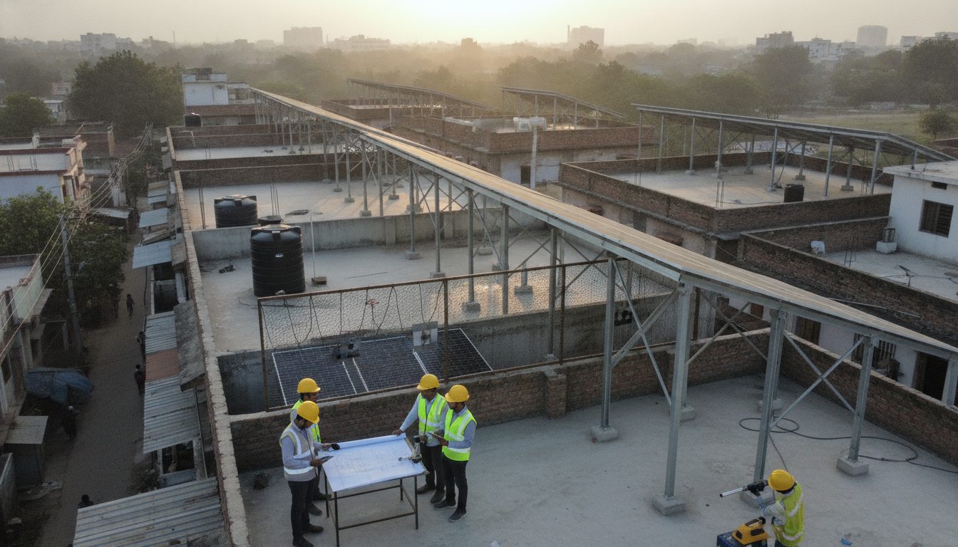
Structural failures during high-speed storms and cyclones are a major liability for solar EPCs. Indian Standards, specifically IS 875 Part 3, dictate wind load parameters based on geographic zones and building height. When engineers calculate the structural requirements for a rooftop array, they evaluate basic wind speed maps of India, terrain categories, and structural risk coefficients. These variables determine the exact pressure exerted on the PV modules and the supporting framework. Homeowners planning a rooftop installation can estimate their structural footprint requirements by checking the solar roof area calculator before finalizing panel placement. Getting these calculations right prevents uplift forces from tearing the mounting system away from the concrete slab or metal sheet during severe weather events.
To check the numbers for your own home, try the solar calculator — enter your electricity bill and get system size, subsidy and payback in seconds.
Galvanized Iron versus Aluminum Mounting Structures
Choosing the right material dictates the long-term integrity of the installation. Galvanized iron (GI) structures offer high mechanical strength and rigidity, making them a common choice for large commercial sites and heavy-duty ground-mount systems. Aluminum structures provide a lighter alternative with high corrosion resistance, which is preferred for coastal residential roofs where salt spray degrades unprotected metal quickly. Each material responds differently to vibrational stress caused by constant wind flow across the panel plane. Engineers must match the material gauge and profile thickness to the specific wind zone classification of the city to avoid metal fatigue over the multi-decade lifespan of the solar power plant.
Ballast Block Sizing for Flat Concrete Roofs
Penetrating a concrete roof to anchor solar panels is not always an option due to waterproofing concerns. Non-penetrating flat concrete roofs rely on gravity mounting systems that use concrete ballast blocks to hold the array down. Sizing these blocks requires precise math that balances the upward lift generated by wind passing over tilted solar panels against the downward gravitational pull of the concrete weights. If the blocks are too light, the array shifts during a storm. If they are too heavy, the structural load limits of the building may be exceeded. Installers calculate the exact weight per support point based on the building height, parapet walls, and local wind speed data.
Tilt-Angle Wind Drag Mitigation
The angle at which solar panels are tilted directly affects the amount of wind drag the mounting structure experiences. Steeper tilt angles capture more wind energy like a sail, increasing the overturning moment on the legs and clamps. To mitigate this risk, commercial and residential sites often optimize tilt angles based on latitude while keeping overall profile heights low. Wind tunnel tests and computational fluid dynamics help engineers design aerodynamic wind deflectors or wind screens on the perimeter of the array. These additions break up laminar airflow and reduce negative pressure zones behind the leading edge of the solar field.
🌟 Ready to Go Solar? Get 3 Free Quotes
Connect with verified, MNRE-empanelled solar installers near you — free, no obligation.
Get Free Solar Quotes →