 SolarCalculators
Plastics & Injection Molding Plant Rooftop Solar: Hydraulic Motor Surges, Zero-Export & 2.1-Year Payback 2026
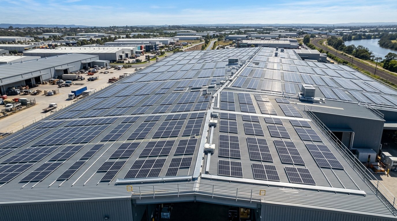
1. The Electrical Anatomy of an Injection Molding Cycle
An injection molding machine operates through a cyclical, non-linear thermodynamic and mechanical process spanning 15 to 90 seconds per cycle:
| Cycle Phase | Mechanical / Thermal Operation | Electrical Demand Characteristic | Solar Generation Alignment |
|---|---|---|---|
| 1. Mold Clamping | Hydraulic cylinders lock heavy steel mold platens under 100 to 1,500 tons of clamping force | Massive instantaneous surge (2.5x to 4x rated motor current) lasting 2–4 seconds | Supplied by inverter dynamic headroom + grid buffer |
| 2. High-Pressure Injection | Hydraulic screw rams molten polymer (PP, HDPE, ABS) into mold cavity at 1,500–2,000 bar | Continuous high-torque motor load at near peak nameplate kW | 100% Offset by peak afternoon solar PV generation |
| 3. Cooling & Plasticizing | Chiller water circulates through mold while screw rotates to melt fresh resin pellets | Steady, moderate mechanical load + barrel ceramic heater band cycling | High base load matching continuous solar output |
| 4. Mold Opening & Ejection | Platens open and pneumatic/hydraulic ejector pins push finished parts onto conveyors | Sharp short burst followed by near-instantaneous load drop to idle (\(< 15\%\) load) | Risk of momentary reverse-power export if unmanaged |
2. The Challenge of Hydraulic Surges & Zero-Export Throttling
When multiple injection molding machines cycle in unsynchronized succession, factory-wide power demand exhibits rapid sawtooth fluctuations. If a plant has an off-net-metering or zero-export connection with the local DISCOM (e.g., MSEDCL, UGVCL, or BESCOM), this dynamic creates severe operational risks:
The Reverse Power Trip Hazard: If three large 500-ton molding machines suddenly transition from injection to mold cooling simultaneously while the rooftop solar plant is producing 500 kW at midday, local factory load may plummet from 650 kW down to 220 kW within 400 milliseconds. Without millisecond-fast control, excess solar power instantly flows back toward the utility transformer, triggering the DISCOM's reverse-power relay and tripping the main circuit breaker!
Fast-Response Zero-Export Control: Industrial solar plants on injection molding facilities must utilize dedicated High-Speed Zero-Export Power Plant Controllers (PPCs) connected via fiber-optic Modbus TCP or Ethernet/IP with current transducer (CT) sampling rates exceeding 50 Hz (20 ms response). The PPC dynamically modulates inverter active power setpoints via SunSpec fast-throttle registers, preventing back-feeding within 150 milliseconds.
3. Mitigating VFD Harmonics & Power Factor Penalties
Modern servo-hydraulic injection molding machines use variable frequency drives (VFDs) to control hydraulic pump motors. While VFDs save significant energy compared to older fixed-displacement pumps, their 6-pulse or 12-pulse rectifiers inject severe harmonic currents:
- Total Harmonic Distortion (THD): Total current harmonic distortion (\(\text{THD}_i\)) in plastics facilities often exceeds 22% to 35%, dominated by the 5th (250 Hz) and 7th (350 Hz) harmonics.
- Inverter PLL Instability: High voltage THD causes distortion of the AC sinusoidal waveform, causing solar string inverters to suffer Phase-Locked Loop (PLL) tracking errors and nuisance grid-overvoltage / frequency trips.
- Active Harmonic Filters (AHF): Installing dynamic Active Harmonic Filters at the main LT bus injects counter-phase harmonic compensation currents within microseconds, reducing factory \(\text{THD}_i\) to below 4.0% (well within IEEE 519 compliance) and maintaining a pristine 0.99 lag Power Factor to capture DISCOM power factor incentives.
4. Financial Blueprint: 500 kWp Rooftop Solar on a Plastic Molding Plant
Let us examine the project economics for a mid-sized automotive plastic components factory located in Chakan, Pune (MSEDCL Industrial HT-I Tariff):
| Financial / Technical Metric | Engineering Value | Operational Impact |
|---|---|---|
| Rooftop Solar Plant Capacity | 500 kWp (Mono-PERC / TOPCon 580Wp) | Fitted on 42,000 sq.ft. PEB Standing Seam Roof |
| Annual Clean Energy Generation | 7,30,000 kWh (Units) / Year | Specific yield: 1,460 kWh/kWp/year |
| Displaced Industrial Grid Tariff | ₹8.85 / kWh (Blended daytime + TOD peak) | Direct reduction of daytime billing slab |
| Gross Annual Electricity Bill Savings | ₹64,60,500 / year | Over ₹5.38 Lakhs saved every single month |
| Turnkey CAPEX Investment | ₹1,75,00,000 (@ ₹35/Watt including AHF + PPC) | Tier-1 inverters, structure, cabling & CEIG approvals |
| Year 1 Tax Benefit (Section 32 Accelerated Dep.) | ₹28,00,000 (40% WDV Depreciation @ 25.17% Corp Tax) | Direct cash flow tax shield in Year 1 |
| Net Effective Project Cost | ₹1,47,00,000 | After deducting Year 1 tax cash savings |
| Simple Payback Period | 2.1 Years (25 Months) | 22.9 Years of virtually free clean power thereafter |
5. Roof Integrity & Clamp Engineering on PEB Sheds
Plastic molding facilities generate substantial internal heat from hydraulic power packs and heating barrels, requiring continuous roof exhaust louvers. When mounting solar arrays:
- Non-Penetrating Seam Clamps: Use aircraft-grade extruded aluminium standing-seam clamps with EPDM gaskets. Zero self-tapping screws are permitted to penetrate the roof sheet, eliminating the risk of rainwater leaks onto high-precision CNC molds and robotics.
- Thermal Vent Clearance: Maintain a 2.5-meter exclusion buffer around all roof exhaust vents to prevent hot air plumes (which can reach 60°C) from degrading solar module efficiency through high temperature coefficients.