 SolarCalculators
Solar Array Shading Analysis & 3D LiDAR Modeling: Near vs Far Shading (PVsyst Guide) 2026
1. Near Shading vs Far-Field (Horizon) Shading
Photovoltaic yield modeling tools (such as PVsyst, Helioscope, and Aurora Solar) treat environmental obstructions under two distinct mathematical formulations:
| Dimension | Near Shading (3D Scene Modeling) | Far-Field / Horizon Shading |
|---|---|---|
| Obstruction Distance | Within the immediate vicinity of the array (typically \(< 50\,\text{meters}\)) | Distant landscape obstructions (typically \(> 50 - 100\,\text{meters}\) to kilometers) |
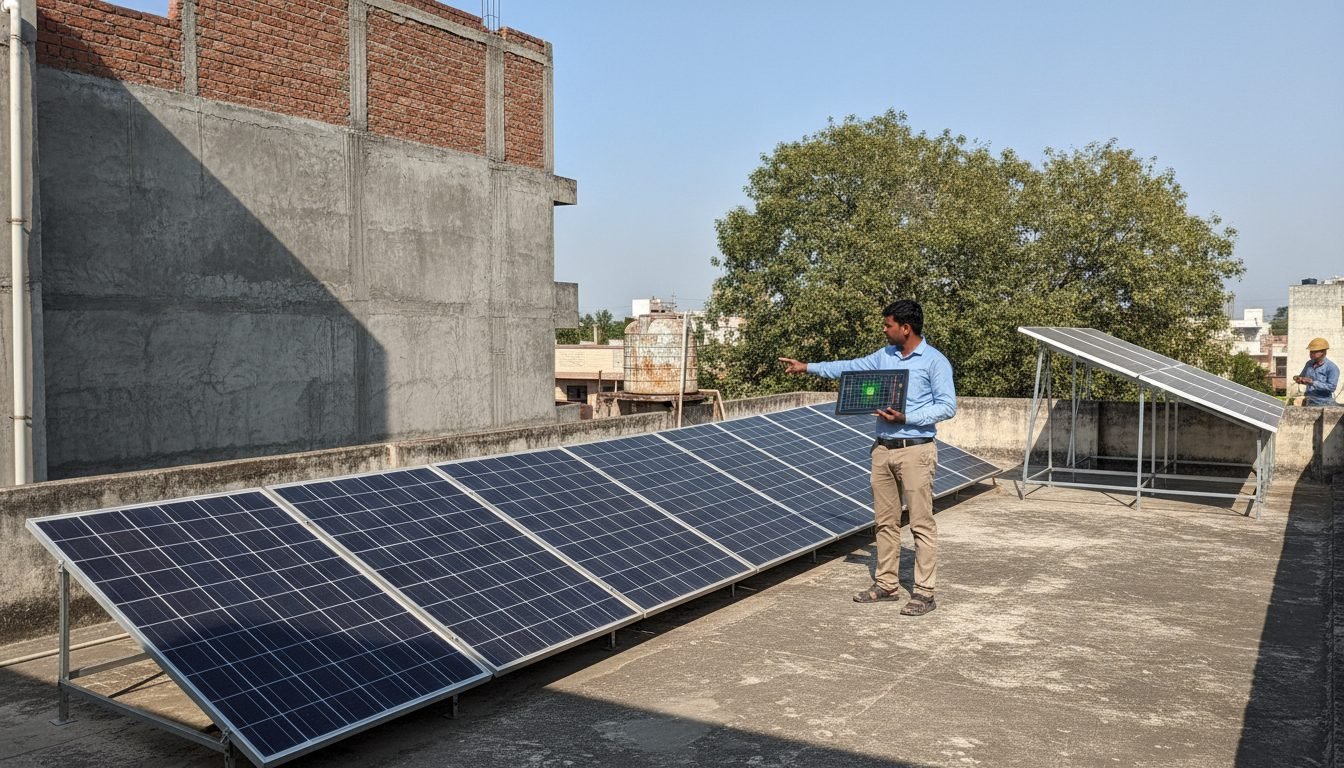
| Typical Obstacle Types | Parapet walls, staircases, water tanks, HVAC chillers, chimneys, nearby trees, and adjacent module rows | Mountains, hills, dense distant forests, and neighboring high-rise skylines |
| Optical Shadow Nature | Produces crisp geometric shadows (umbra and penumbra) with strong spatial irradiance gradients | Causes uniform global delay in morning sunrise or premature evening sunset across the entire array |
| Electrical Impact | Highly non-linear: Triggers bypass diodes, creates multi-peak P-V curves, and induces hotspot heating | Linear: Drops overall global irradiance uniformly without inducing intra-string mismatch |
2. 3D Drone LiDAR & Photogrammetry Point Cloud Modeling
Traditional manual measuring tape and compass surveys are notorious for overlooking critical roof obstructions (such as hidden vent pipes, guy wires, or overhead HT transmission cables). Modern EPC engineering deploys RTK-enabled camera drones to capture high-density 3D digital twins:
- Dense Point Cloud Generation: Photogrammetry software (e.g., Pix4D, DJI Terra) processes hundreds of georeferenced aerial photos, generating millions of 3D spatial points with centimetre-level accuracy (\(\le 2\,\text{cm}\)).
- Direct CAD / PVsyst Import: The resulting 3D mesh is exported as a standard
.OBJor.DXFfile and imported directly into PVsyst’s 3D Scene Editor. Every parapet wall, tree canopy, and AC compressor is positioned with absolute physical precision. - Year-Round Sun-Path Ray Tracing: The simulation engine casts sunlight rays at 15-minute intervals across 365 days, computing exact diffuse and beam shading factors (\(F_{\text{beam}}\) and \(F_{\text{diffuse}}\)) for every square centimeter of the array.
3. Inter-Row Pitch Optimization: The Winter Solstice Standard
The single most controllable cause of near-field shading in multi-row ground-mount and flat-roof solar installations is row-to-row self-shading. When the front row of tilted solar modules casts a shadow backward onto the lower cells of the second row:
The Golden Engineering Rule (December 21 Solstice):
In the Northern Hemisphere, the sun reaches its lowest solar elevation angle (\(\alpha\)) on the Winter Solstice (December 21). If rows do not shade each other between 09:00 AM and 03:00 PM on December 21, the installation is guaranteed 100% shadow-free operation for the remainder of the year.
Minimum Inter-Row Spacing Formula:
\[D = L \times \left( \frac{\sin(\beta)}{\tan(\alpha)} \times \cos(\gamma) + \cos(\beta) \right)\]- \(D\) = Minimum row-to-row pitch (distance between table front edges).
- \(L\) = Length of the tilted module table along the slant.
- \(\beta\) = Module tilt angle (degrees).
- \(\alpha\) = Solar elevation angle at 09:00 AM / 03:00 PM on December 21.
- \(\gamma\) = Solar azimuth angle difference relative to true South.
4. Mitigation Strategies for Unavoidable Shading
When physical obstructions (such as elevator machine rooms or towering industrial silos) cannot be avoided, engineering layout design mitigates power collapse through three proven architectures:
- Portrait vs Landscape Module Orientation: Standard half-cut cell modules (144 cells) feature internal bypass diodes dividing the panel lengthwise. In Landscape Orientation, a horizontal shadow creeping up from the bottom edge cuts only 50% of the module output, whereas in Portrait Orientation, a horizontal shadow cuts across all three sub-strings, shutting down 100% of the module output.
- Multi-MPPT Inverter String Allocation: Never connect shaded strings and unshaded strings into the same Maximum Power Point Tracker (MPPT). Dedicated MPPT channels isolate shaded string voltage drops without dragging down healthy arrays.
- DC Module Optimizers (e.g., SolarEdge, Tigo): On complex residential roofs with irregular chimney shadows, DC-DC optimizers operate each module at its independent peak power point, allowing unshaded modules in the string to produce full power unimpeded.