 SolarCalculators
Solar Plant Commissioning & Handover Testing: IEC 62446-1 Category 1 & 2 Checklist 2026
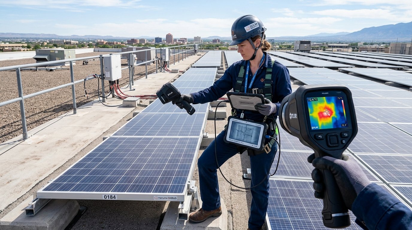
1. The Two Testing Regimes Under IEC 62446-1
The International Electrotechnical Commission standard defines two hierarchical levels of commissioning validation:
- Category 1 Tests (Mandatory for ALL Systems): Baseline electrical safety and continuity tests that must be executed and documented on every single installed PV string before energization.
- Category 2 Tests (Recommended for Systems > 100 kW & Utility): In-depth performance characterization tests, including high-accuracy I-V curve tracing and radiometric thermal imaging under load.
| Testing Category | Specific Test Procedure | Standard Acceptance Criteria | Instrumentation Required |
|---|---|---|---|
| Category 1 | Earthing / Protective Bonding Continuity | Resistance \(\le 0.5\,\Omega\) between all module frames, MMS, and earth bus | Calibrated Micro-Ohmmeter / 200mA Continuity Tester |
| Category 1 | DC String Polarity Check | Strict positive and negative identification; zero reverse polarity | Digital Multimeter (1000V/1500V DC rated) |
| Category 1 | String Open-Circuit Voltage (\(V_{\text{oc}}\)) | Measured \(V_{\text{oc}}\) within ± 5% of calculated STC value across parallel strings | Multimeter + Handheld Pyranometer |
| Category 1 | String Short-Circuit Current (\(I_{\text{sc}}\)) | Measured \(I_{\text{sc}}\) within ± 5% across identical irradiance conditions | DC Clamp Meter / Short-Circuit Switch Box |
| Category 1 | DC Insulation Resistance (\(R_{\text{iso}}\)) | \(\ge 1.0\,\text{M}\Omega\) (1000V DC test) between live conductors and ground | 1000V/1500V Megohmmeter (Megger) |
| Category 2 | String I-V Curve Tracing | Fill Factor (FF) \(\ge 0.75\); no inflection steps or slope anomalies | Precision Solar I-V Curve Tracer with Reference Cell |
| Category 2 | Radiometric Thermography Under Load | No cell hotspot \(\Delta T > 15^\circ\text{C}\) at \(\ge 700\,\text{W/m}^2\) irradiance | Calibrated Thermal Imaging Camera (NETD \(\le 40\,\text{mK}\)) |
2. Detailed Step-by-Step Category 1 Testing Protocols
- Polarity Verification: Accidental reverse polarity on even a single string can cause catastrophic inverter DC capacitor explosion or permanent MPPT tracker failure upon connection. Measure voltage between (+) and (-) terminals of each string before insertion into combiner boxes or inverters. Multimeter display must show positive voltage with red probe on positive conductor.
- Open-Circuit Voltage (\(V_{\text{oc}}\)) Consistency Test: \[V_{\text{oc,expected}} = N_{\text{modules}} \times V_{\text{oc,STC}} \times \left[1 + \beta \times (T_{\text{cell}} - 25^\circ\text{C})\right]\] Compare all parallel strings sharing an MPPT tracker. A string reading \(40\text{V} - 50\text{V}\) lower than adjacent strings indicates a completely disconnected or bypassed module.
- Earth Fault Loop Impedance: Measure total earth pit loop resistance with a 4-terminal Digital Earth Resistance Tester using the Fall-of-Potential method. Individual chemical earth pits must measure \(\le 2.0\,\Omega\), and the integrated grid earth loop must measure \(\le 1.0\,\Omega\).
3. Category 2: I-V Curve Tracing & Thermal Imaging
While basic voltage checks confirm whether a string is connected, they reveal zero information about internal cell microcracking, high solder resistance, or PID degradation:
I-V Curve Tracing Analysis: A handheld curve tracer (e.g., Seaward PV200, HT Instruments, or Solmetric PVA) sweeps the full I-V curve from \(I_{\text{sc}}\) to \(V_{\text{oc}}\) in milliseconds, automatically normalizing measurements to Standard Test Conditions (STC: \(1000\,\text{W/m}^2\), \(25^\circ\text{C}\)):
- Reduced Slope near \(V_{\text{oc}}\): Indicates abnormally high series resistance (\(R_s\)) caused by loose MC4 crimps, undersized DC cables, or internal busbar corrosion.
- Steeper Slope near \(I_{\text{sc}}\): Indicates low shunt resistance (\(R_{\text{sh}}\)) caused by localized leakage currents or severe cell microcracks.
- Notched "Staircase" Steps: Conclusive visual fingerprint of bypass diode conduction caused by partial shading or a cracked, inactive cell.
4. CEIG Statutory Clearance & Handover Documentation Package
In India, energization of systems \(\ge 100\,\text{kW}\) requires formal safety inspection and charging permission from the Chief Electrical Inspector to Government (CEIG). The contractor must compile the official Handover Dossier containing:
- As-Built Single Line Diagram (SLD) signed and stamped by an accredited electrical engineer.
- Structural Stability Certificate endorsed by a Chartered Civil/Structural Engineer.
- Factory calibration certificates for all Class 0.2s CT/PT metering units and bidirectional ABT net meters.
- Complete IEC 62446 commissioning test log sheets signed by the commissioning head.
- O&M manuals, warranty certificates (12-year product / 25-30 year performance warranties), and 24x7 emergency contact protocols.