 SolarCalculators
Solar PV Dynamic Cable Rating & Temperature Derating (IS 7098 / IEC 60364-5-52): Tray Grouping & Sizing Guide 2026
1. The Cable Heat Balance Equation & Continuous Ampacity
The continuous current-carrying capacity (\(I_z\)) of an insulated electrical cable is governed by the steady-state thermal equilibrium between internal Joule heating and outward heat dissipation to the surrounding ambient medium:
\[I_z = I_0 \times k_1 \times k_2 \times k_3 \times k_4\]Where:
- \(I_0\): Base continuous current-carrying capacity at a reference ambient temperature (typically 30°C in air under IEC 60364-5-52 or IS 7098).
- \(k_1\): Temperature correction derating factor based on actual ambient and surface exposure.
- \(k_2\): Cable grouping and proximity reduction factor (accounting for mutually radiating adjacent circuits).
- \(k_3\): Installation method factor (open-air ladder tray vs perforated tray vs solid conduit).
- \(k_4\): Solar radiation thermal absorption coefficient for non-UV-shielded exterior conduits.
| Ambient / Enclosure Air Temp (°C) | PVC Insulation (Max 70°C) Correction \(k_1\) | XLPE / Cross-Linked Polyolefin (Max 90°C) Correction \(k_1\) | Solar DC Cable (EN 50618, Max 120°C) Correction \(k_1\) |
|---|---|---|---|
| 30°C (Standard Lab Base) | 1.00 | 1.00 | 1.00 |
| 45°C (Indian Summer Shade) | 0.79 | 0.87 | 0.92 |
| 55°C (Rooftop Elevated Tray) | 0.61 | 0.76 | 0.84 |
| 65°C (Direct Metal Sheet / Unventilated Conduit) | 0.35 (Thermal Breakdown) | 0.65 | 0.75 |
| 75°C (Closed Combiner Box Internal) | UNSAFE (Melts) | 0.50 | 0.65 |
2. Proximity & Grouping Derating Factors (\(k_2\)) on Cable Trays
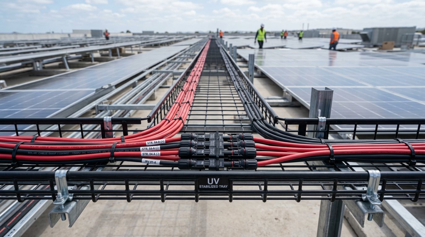
In large MW-scale rooftop and utility-scale installations, dozens of positive and negative DC string cables are bundled together inside cable trays. When current flows simultaneously through tightly packed cables, trapped heat cannot dissipate effectively:
Touching vs Spaced Installation: Under IEC 60364-5-52 (Table B.52.17), if 6 multi-core cables or 6 DC string pairs are laid touching each other on a perforated cable tray, the grouping derating factor drops to \(k_2 = 0.72\). If 12 circuits are bundled, \(k_2\) plummets to 0.55!
The One-Diameter Spacing Rule (\(2 \times d\)): By maintaining a physical clearance equal to at least one cable diameter between adjacent cables, the grouping factor \(k_2\) remains at 0.95 to 1.00, allowing engineers to utilize full cable ampacity and avoid unnecessary cross-sectional conductor oversizing.
3. Mathematical Case Study: Sizing a 1,500V DC Solar String Cable Run
Let us analyze a real-world engineering calculation for a 600 kWp rooftop solar plant in Ahmedabad, Gujarat:
- Module Specs: 580 Wp TOPCon modules with \(I_{\text{mp}} = 13.8\,\text{A}\) and \(I_{\text{sc}} = 14.6\,\text{A}\).
- Continuous Operating Design Current: Per NEC / IEC 62548, design current must incorporate irradiance overshoot: \[I_{\text{design}} = 1.25 \times I_{\text{sc}} = 1.25 \times 14.6\,\text{A} = 18.25\,\text{A}\]
- Rooftop Environment: Galvanized cable tray mounted 100 mm above Klip-Lok PEB roof sheets. Peak measured summer tray temperature = 58°C. Cables bundled in groups of 4 pairs touching.
- Applied Derating Factors: \[k_1 (\text{at } 58^\circ\text{C for EN 50618 120}^\circ\text{C cable}) \approx 0.81\] \[k_2 (\text{4 bundled circuits touching}) \approx 0.77\] \[k_{\text{total}} = k_1 \times k_2 = 0.81 \times 0.77 = 0.6237\]
- Required Catalog Base Ampacity (\(I_0\)): \[I_0 \ge \frac{I_{\text{design}}}{k_{\text{total}}} = \frac{18.25\,\text{A}}{0.6237} = 29.26\,\text{A}\]
- Conductor Selection:
- Standard \(4.0\,\text{mm}^2\) tinned copper solar DC cable has a nominal in-air ampacity of \(44\,\text{A}\). Derated ampacity: \(44\,\text{A} \times 0.6237 = 27.44\,\text{A}\) (Fails safety margin! Under-rated under peak conditions).
- Upgrading to \(6.0\,\text{mm}^2\) tinned copper cable provides a nominal base ampacity of \(58\,\text{A}\). Derated ampacity: \(58\,\text{A} \times 0.6237 = 36.17\,\text{A}\) (Passes comfortably with a 1.98x safety factor).
4. Voltage Drop (\(\Delta V\)) Optimization vs Capital Cost
While thermal ampacity dictates physical fire safety, voltage drop (\(\Delta V\)) dictates 25-year financial energy yield. Every millivolt lost across DC cabling is converted directly into wasted heat:
\[\Delta V = \frac{2 \times L \times I \times \rho_{\text{conductor}}}{A}\]Where \(L\) is the one-way route length in meters, \(I\) is operating current (\(I_{\text{mp}}\)), \(\rho_{\text{conductor}}\) is resistivity (\(0.01786\,\Omega\cdot\text{mm}^2/\text{m}\) for copper at 20°C, adjusted to \(0.022\,\Omega\cdot\text{mm}^2/\text{m}\) at 70°C operating temperature), and \(A\) is cross-sectional area in \(\text{mm}^2\).
The 1.5% Gold Standard: Best-practice engineering mandates keeping total DC voltage drop strictly under 1.0% to 1.5% from the farthest solar module to the inverter MPPT terminals. For long rooftop cable routes exceeding 75 meters, selecting \(6.0\,\text{mm}^2\) or \(10.0\,\text{mm}^2\) conductors pays for itself within 18 months through saved kilowatt-hours.
5. Best-Practice Installation Checklist for EPCs
- Elevated Trays: Always mount cable trays on non-penetrating UV-stabilized rubber or aluminium sleepers at least 100 mm to 150 mm above the roof deck to ensure natural convective air cooling beneath the tray.
- Perforated Trays with Covers: Use hot-dip galvanized (HDG) perforated trays with ventilated louvered covers to block direct solar radiation while allowing hot air to escape freely.
- UV & Ozone Resistant Ties: Fasten cables using stainless steel (SS 316) cable ties with protective polymer coatings or heavy-duty UV-stabilized nylon 12 ties. Standard white indoor zip ties embrittle and snap within 6 months.