 SolarCalculators
Solar Soil Resistivity Testing (Wenner 4-Pin) & Earthing Grid Design: IEEE 80 Guide 2026
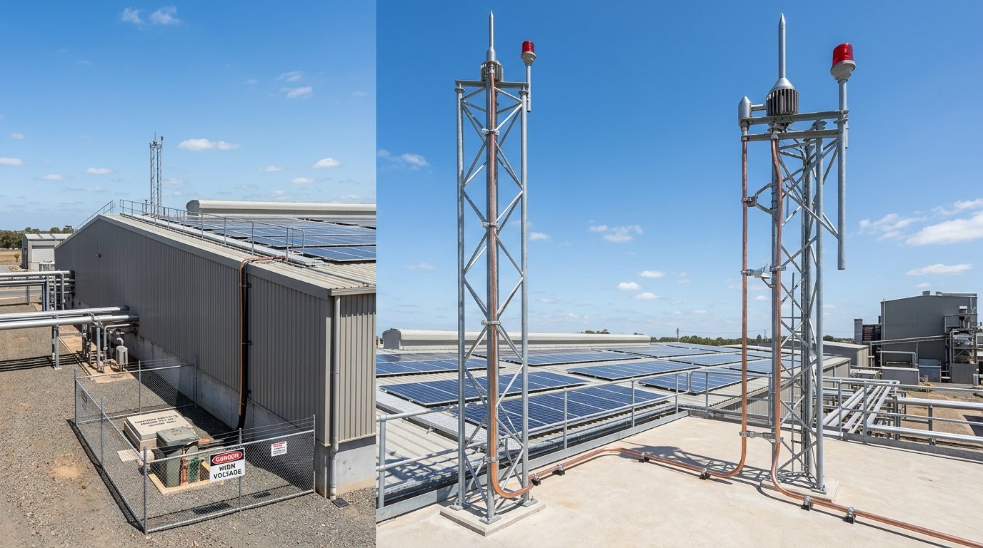
1. The Physics of Soil Resistivity & The Wenner 4-Pin Array
Soil is not a uniform electrical conductor; its resistivity varies drastically across geological depths, moisture gradients, and chemical mineral content. Dr. Frank Wenner's 4-Pin method (developed at the US Bureau of Standards) is the global benchmark under IEEE 81 and IS 3043:
- Electrode Arrangement: Four straight, equidistant metal electrode pins are driven into the ground in a line at depth \(b \le 0.05 \times a\) (where \(a\) is the inter-pin spacing).
- Current Injection & Potential Measurement: A calibrated 4-terminal Digital Earth Tester (e.g., Megger DET2/3 or Chauvin Arnoux) injects low-frequency AC test current (\(I\)) between the outer two pins (\(C_1\) and \(C_2\)) and measures the resultant potential difference (\(V\)) between the inner two pins (\(P_1\) and \(P_2\)).
- The Wenner Resistivity Formula: \[\rho_a = 2 \pi a R\] Where \(\rho_a\) is the apparent soil resistivity in \(\Omega\cdot\text{m}\), \(a\) is the pin separation distance in meters, and \(R = V/I\) is the measured resistance in \(\Omega\).
- Depth Exploration Relationship: The inter-pin spacing (\(a\)) roughly corresponds to the soil depth being measured. Testing at spacings of \(a = 1\text{m}, 2\text{m}, 3\text{m}, 5\text{m}, 10\text{m}, 15\text{m}\) reveals the geological resistivity profile from shallow topsoil down to deep bedrock.
| Soil Type / Geology | Typical Resistivity (\(\Omega\cdot\text{m}\)) | Corrosivity Risk | Earthing Design Challenge |
|---|---|---|---|
| Marshy ground, swamp, wet black cotton soil | \(10 - 50\,\Omega\cdot\text{m}\) | High (Acidic moisture requires HDG or copper-bonded steel) | Low grid resistance easily achieved; minimal backfill required |
| Agricultural clay / loam | \(50 - 150\,\Omega\cdot\text{m}\) | Moderate | Standard chemical earth pits deliver \(\le 1.0\,\Omega\) with standard conductor spacing |
| Sandy soil / desert sand (Rajasthan) | \(250 - 800\,\Omega\cdot\text{m}\) | Low (Very dry) | Extremely poor conductivity; requires deep vertical bore pits and carbonaceous conductive backfill |
| Rocky terrain, shale, Deccan basalt granite | \(1,000 - 5,000+\,\Omega\cdot\text{m}\) | Very Low | Vertical driving impossible; requires dense horizontal loop mesh, counterpoise wires, and chemical compounds |
2. Two-Layer Soil Modeling: Topsoil vs Subsoil
Uniform soil rarely exists in nature. In most commercial solar sites, soil resistivity curves exhibit either an increasing profile (low-resistance wet topsoil over dense bedrock) or a decreasing profile (parched topsoil over a moist high-water table):
IEEE 80 Two-Layer Formulation: The earth grid is modeled with an upper layer of depth \(h\) and resistivity \(\rho_1\), and an infinite lower layer of resistivity \(\rho_2\). The reflection factor \(K\) dictates current diffusion:
\[K = \frac{\rho_2 - \rho_1}{\rho_2 + \rho_1}\]If \(K > 0\) (rocky bottom layer), lightning and fault currents reflect upward toward the surface, dramatically increasing hazardous surface Touch and Step voltages unless suppressed by a thick crushed-rock surface layer.
3. Step & Touch Potential Safety Limits (IEEE 80-2013)
The primary purpose of a solar grounding grid during a 33kV HT phase-to-ground fault or lightning strike is to keep surface voltage differentials below thresholds that cause ventricular fibrillation in a human body:
- Touch Potential (\(E_{\text{touch}}\)): The potential difference between the grounded metal equipment frame (touched by hand) and a point on the ground surface \(1.0\,\text{meter}\) away (where the feet stand).
- Step Potential (\(E_{\text{step}}\)): The potential difference between two points on the ground surface separated by a distance of \(1.0\,\text{meter}\) (one human step).
- Crushed Rock Layer (Gravel Insulation): Spreading a 100mm to 150mm layer of clean, washed crushed granite rock (\(\rho_{\text{gravel}} \ge 3,000\,\Omega\cdot\text{m}\)) inside the solar plant inverter and substation yards increases human foot contact resistance, raising safe touch voltage tolerance from \(400\text{V}\) to over \(1,800\text{V}\).
4. Sizing the Grounding Conductor: Copper vs Galvanized Steel
| Conductor Parameter | Copper-Bonded Steel Rods (254\(\mu\)m) | Hot-Dip Galvanized (HDG) Steel Flat |
|---|---|---|
| Electrical Conductivity | 20% to 40% IACS | 8.5% to 10% IACS |
| Required Cross-Section for 25kA / 1s | \(95 - 120\,\text{mm}^2\) | \(300 - 400\,\text{mm}^2\) (\(50 \times 6\,\text{mm}\) or \(50 \times 8\,\text{mm}\) flat) |
| Corrosion Allowance Factor | Negligible (Copper molecularly bonded) | Must add 1.5mm to 2.0mm sacrificial steel thickness for 25-year design life |
| Theft Risk on Remote Sites | Extremely Low (Zero scrap copper value) | Low (Cheap structural steel) |
| Joint Reliability | Exothermic welding (Cadweld) / compression clamp | Continuous lap-welded joints sealed with anti-corrosion cold bitumen paint |